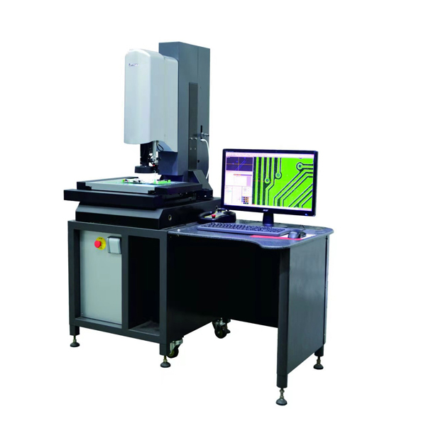
EVM-4030 semi-automatic high-definition image measuring instrument (coaxial light)
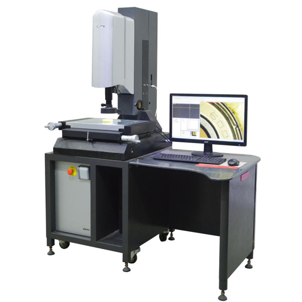
Technical Parameters
|
Specifications Model: EVM-4030
|
|
Measuring range (mm)
|
Dimensions (mm)
|
Host weight (Kg)
|
Maximum bearing weight (Kg)
|
|
X
|
Y
|
Z
|
L
|
W
|
H
|
|
400
|
300
|
250
|
1800
|
1200
|
1900
|
390
|
20
|
|
measurement accuracy
|
|
Optical one-dimensional length measurement error: EU X/Y(1D)(μm)
|
2.0+L/200 MPE complies with JJF 1318-2011
|
|
Optical two-dimensional length measurement error: EU XY(2D)(μm)
|
2.5+L/200 MPE complies with JJF 1318-2011
|
|
Two-dimensional detection error: PF2D(μm)
|
2.5 MPE complies with JJF 1318-2011
|
|
Image probe detection error: PFV2D(μm)
|
2.5 MPE complies with JJF 1318-2011
|
|
Serial number
|
Name
|
Specification and description
|
|
1
|
Host and machine
|
The main body of the fuselage is made of high-precision natural granite, which has stable temperature characteristics and resistance to aging deformation.
|
|
2
|
Control System
|
USB network board to ensure the stability and safety of the machine
|
|
3
|
Easson measurement software system
|
Automatic version of optical vision measurement software
|
|
4
|
Camera
|
1.3 million digital high-definition web camera
|
|
5
|
Grating ruler
|
0.01μm absolute grating
|
|
6
|
Guide
|
The three axes adopt precision ball screw guides, the speed is greatly improved, and the operation is stable
|
|
7
|
Motor
|
DC servo motor
|
|
8
|
Lens
|
Easson independently designed TC precision manual zoom manual zoom telecentric lens (standard coaxial light) actual magnification: 30-145×
|
|
9
|
Lighting system
|
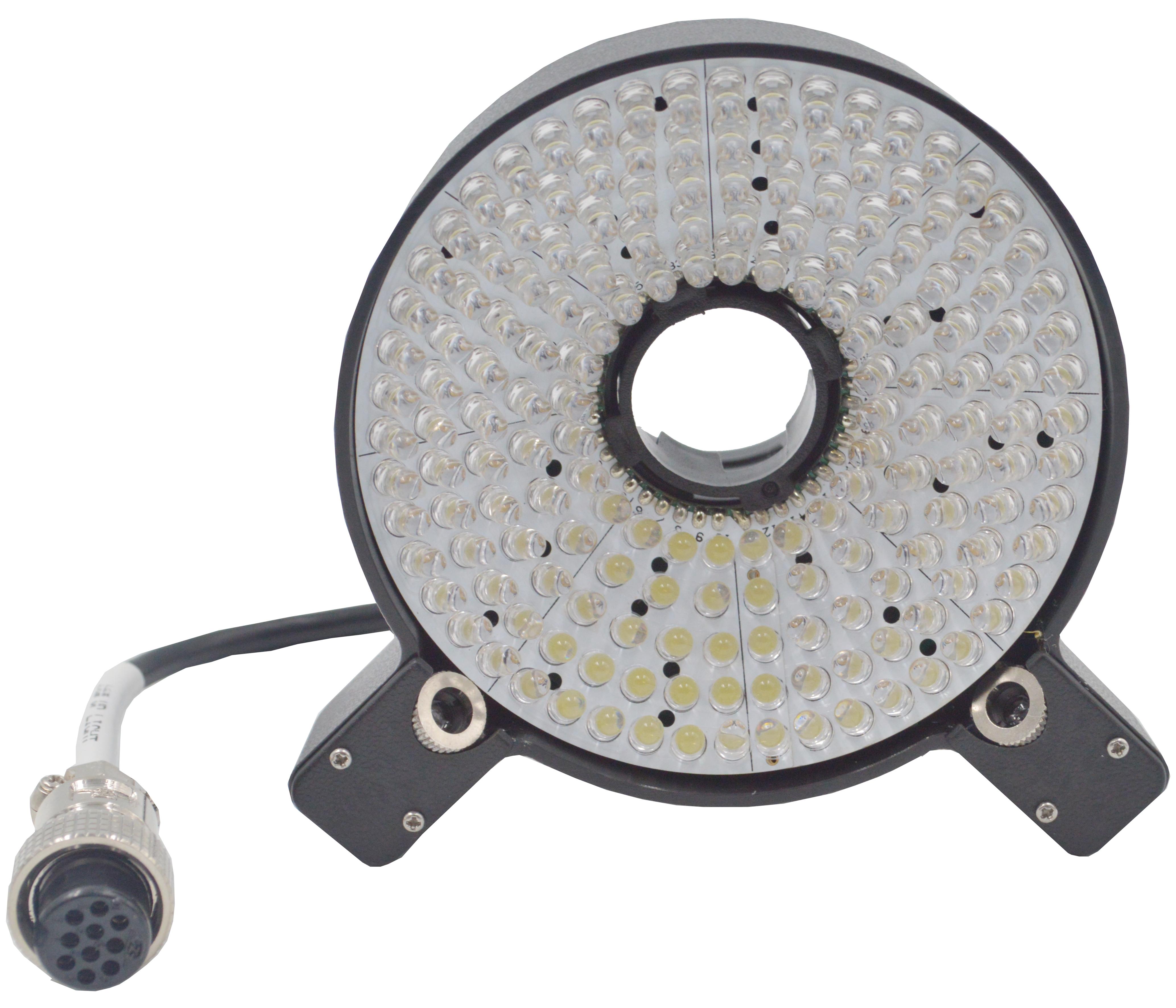
5 rings and 8 zones LED cold light source is independently controlled for each segment, 256 levels of brightness adjustable
|
|
10
|
Brand Computer
|
WIN7/WIN10
|
|
23.8 HD
|
|
11
|
Operation method
|
232 control box, mouse hauling, keyboard control
|
Environmental conditions and requirements
|
The temperature requirements of the imager room:
|
|
Room temperature (temperature control room)
|
18~22°C
|
|
Temperature gradient (time)
|
1°C /h
|
|
Temperature gradient (time)
|
2°C /24h
|
|
Temperature gradient (space)
|
1°C /m
|
|
Humidity requirements for imaging room:
|
|
relative humidity
|
40-70%
|
|
Power requirements:
|
|
Voltage
|
220V ± 10%
|
|
frequency
|
50/60 Hz
|
|
shock
|
Below 15Hz<0.001g
|
|
power consumption
|
1000VA
|
|
Electrical equipment requires reliable grounding: the grounding resistance is less than 4 ohms
|
3. Software features
Introduction to the main functions of the smart measurement software Easson2D
1. Basic functions:
●Cartesian coordinate/polar coordinate conversion ●Absolute/relative/working coordinate conversion
●Metric/English conversion ●Degree/degree, minute, second conversion
●Point/Point Group ●Two-point/multi-point seeking line
●Three-point/multi-point finding circle and arc ●B-spline line
●The distance between two points ●The average distance between two lines
●The distance between dots and lines ●The distance between two circles
●Circular line distance ●The angle and intersection between two lines
2. Special functions
1. The software controls the light source. The upper light source is a four-phase lamp, and the lower light source is a straight light source, which increases the adaptability of the machine.
2. There is no need to adjust the position for measuring the workpiece, and the software provides coordinate translation, rotation, and position.
3. Mark/move the size directly in the image and geometric area. Straight line trimming and extension function.
4. Geometry zone points, lines, circles/arcs and straight line endpoints, midpoints, circle centers and quadrant points are automatically captured.
5. Adjust the CCD parameter settings to improve the self-adaptive force; remove the burr function to obtain the measurement data correctly.
6. Use the image tool to quickly and automatically grab the boundary points of the basic geometric contours, and directly fit the lines, circles, and arcs.
7. The workpiece in the measurement area is zoomed in and outputted by the camera and converted into (.bmp, .jpg).
8. Measurement data output, converted into WORD (.doc), EXCEL (.xls).
9. SPC function, directly output control chart, process capability index, and convert it into WORD, EXCEL
10. Direct output of mechanical graphics in .dxf format to realize 2D reading function and seamless connection with AutoCAD and other software.
11. Can be transferred to .DXF format files, and compared with the actual workpiece or measurement graphics. And you can directly pick two points in the image area to get the error measurement value.
12. Provide in-plane straightness, roundness, and angle analysis for effective quality inspection
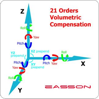
13. The accuracy of the machine is compensated to improve the measurement accuracy.
14. The software can measure multi-deformation, groove shape, arc chamfering and virtual measurement.
15. The 2.5D measurement software can be upgraded, with functions: slope, height, sphere, cylindrical measurement, etc.
16. Re-measurement function: This function can re-change the measurement method, lighting, magnification, etc., for the elements that have been measured, and then refresh the measurement data, and the related element data will also be refreshed (such as: two-line construction distance, if If one of the lines is re-measured, the distance element data will also be refreshed).
17. Modify, edit and view the edge-seeking status: the software can modify and edit the edge-seeking range, light source brightness, magnification, etc. of any measurement element. You can also view the edge-finding status of a certain element measured before (including the position of the edge-finding, the brightness of the light source used, the magnification and the original point taken, etc.), so that the user can control the status of the whole process of measurement.
4. Machine characteristics
The main body of the fuselage is made of high-precision natural granite, which has stable temperature characteristics and anti-aging deformation ability to ensure the stability of measurement and the accuracy of long-term use.
All Yixin's optical image measuring instruments are equipped with the F-1 high-precision full-closed-loop automatic zoom optical lens developed by our company as standard, with high performance and ultra-low distortion to ensure the accuracy of measurement.
High-precision fully closed loop automatic zoom optical lens
The principle of telecentric optics: adopting the optical design of parallel light path, the size of the object image will not change with the distance from the lens, causing the effect of perspective to produce additional measurement errors.
Automatic zoom optical telecentric lens (Telecentric), professionally manufactured by Yixin, is a lens specially designed to correct the parallax of traditional lenses. It can be within a certain object distance range, so that the image magnification will not vary with the object. The distance varies, which is a very important application when the measured object is not on the same surface.
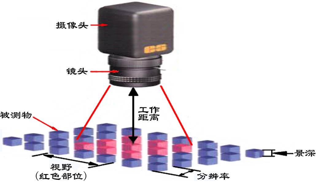
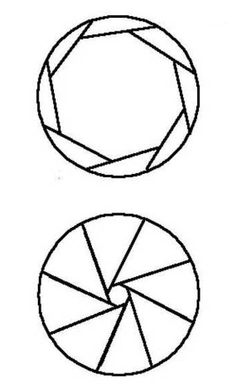
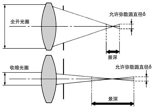
The aperture is a device used to control the amount of light passing through the lens and entering the photosensitive surface of the body. Specifically, if the brightness is high, it can shrink to reduce the total amount of light passing through; on the contrary, if the light is very weak, it can be Make it larger to allow more light to enter. The larger the aperture, the smaller the depth of field; the smaller the aperture, the greater the depth of field. The farther the working distance, the greater the depth of field; the closer the working distance, the smaller the depth of field

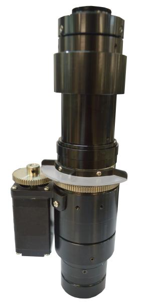
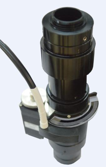
F1 High-precision, fully closed-loop, automatic zoom telecentric lens The features are as follows:
Adopt the high-precision, high-resolution ring-type grating ruler specially developed and designed by our company for F-1 for full closed-loop position feedback
High resolution, fully closed loop position feedback, avoiding the repetition error of image multiples caused by gear transmission gap, greatly improving the repeatability of the whole machine measurement.
The resolution of the ring grating is 20 times higher than that of the previous generation zoom lens.

Yixin telecentric lens VS non-telecentric lens
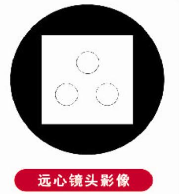
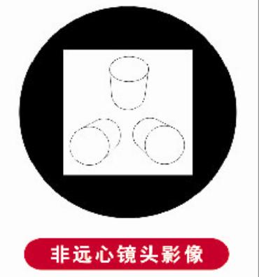
The use of non-telecentric lenses for imaging will produce perspective artifacts and bring test errors.
Use a telecentric lens to correct the image of the light source without distortion and improve the measurement accuracy.
Yixin coaxial optical VS peer non-coaxial optical
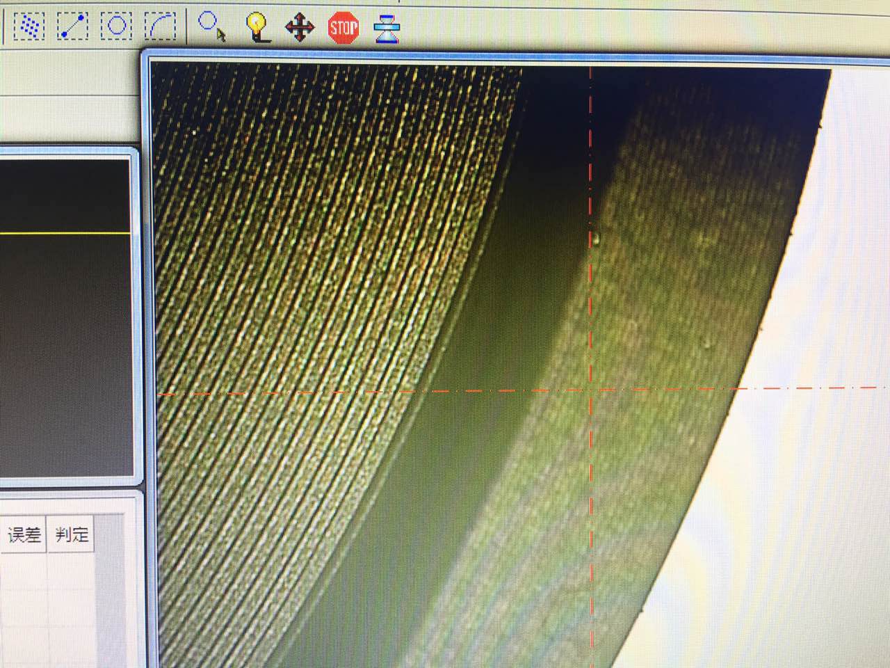
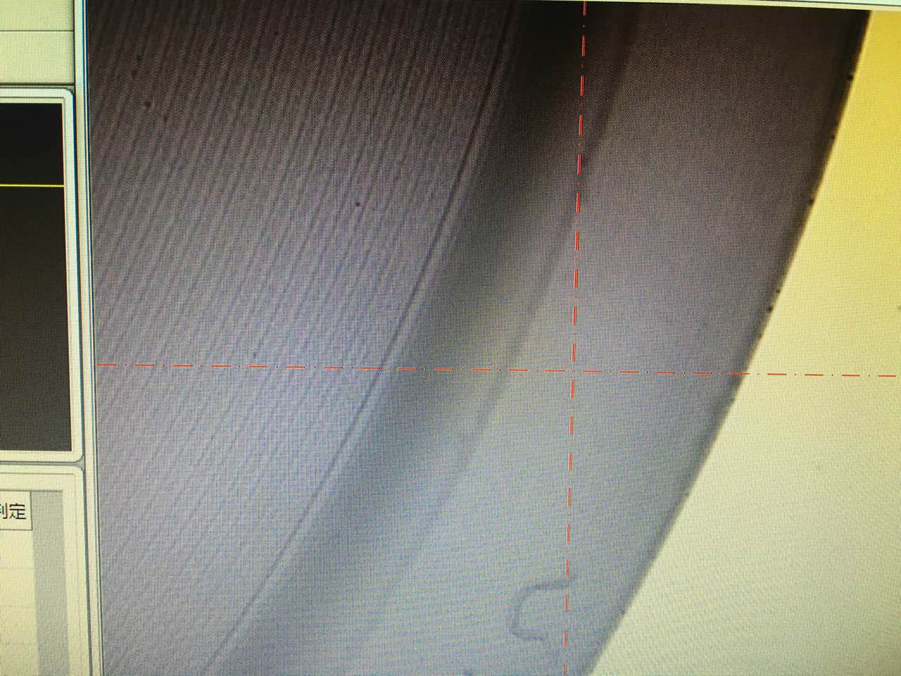
Coaxial optical interface Ordinary light
Yixin high-definition camera VS counterpart ordinary camera
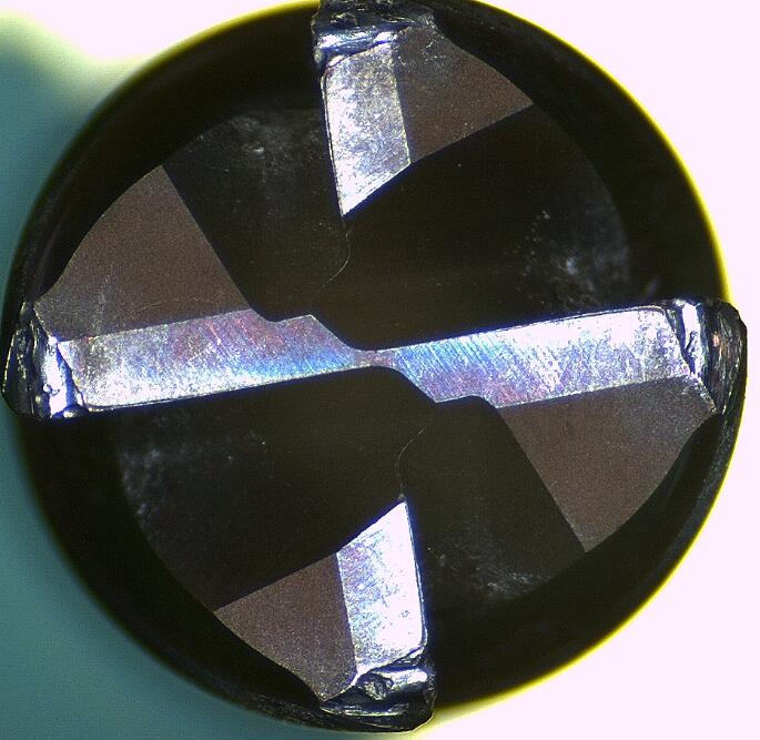

High-definition CCD tool picture for Yixin imager Ordinary CCD tool picture
Yixin absolute grating ruler VS counterpart ordinary grating ruler
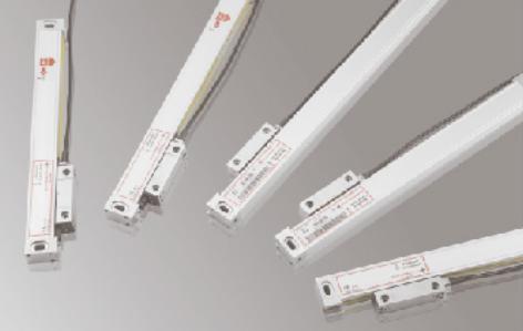
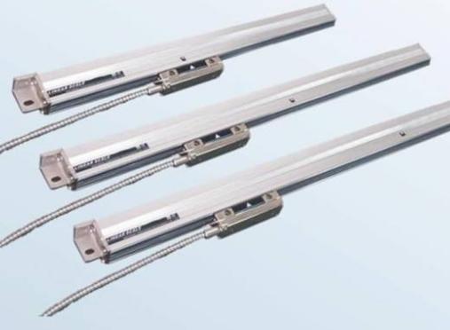
Yixin 0.01um absolute grating ruler, high precision, high resolution 0.5um ordinary grating ruler
Image measuring instrument installation and acceptance standards
1. Equipment acceptance, inventory and installation adjustment test acceptance
1.1 Acceptance of equipment
2.1 Installation and adjustment test acceptance
Packaging and shipping
- Use good wooden box packaging and road transportation to ensure good equipment. The problem of packaging and transportation shall be borne by the seller.
- After the goods arrive at the buyer, the seller’s personnel will arrive at the buyer’s site within one working day to unpack the goods, install and debug the equipment.
Image measuring instrument installation plan and plan, installation, construction organization and personnel situation
Installation plan
Before installing the instrument, please read this "Precautions for Installation"
Installation Precautions:
- Please place this product in a ventilated and dry place, and try to keep the ambient temperature between 20℃-25℃.
- Do not place this product in dusty and humid places.
- This product uses 220V, 50-60HZ AC power supply. This product requires a good connection and grounding of the power supply.
- Please place this product away from strong electric fields or strong electromagnetic interference sources, such as AC cabinets, large machine tools, electromagnets, electric spark machines, etc.
- To ensure measurement accuracy, please place this product away from vibration sources, such as punches, vibrating machines, etc.
- Do not disassemble or adjust product parts by yourself. Do not use accessories not produced or provided by our company.
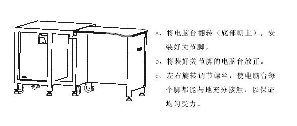
1.Install computer desk
2. Install the electric control box
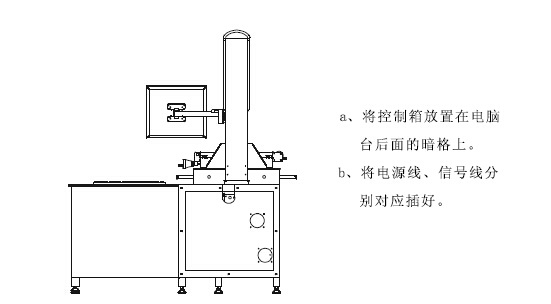
3. Install the computer
a. Very good connection of all parts of the computer.
b. Insert the video cable from the 2D body into the AV1 port of the computer video interface
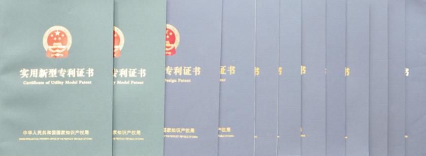
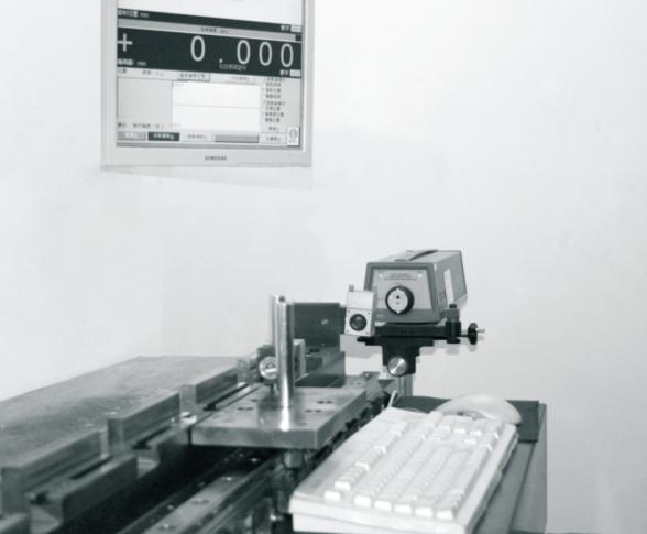
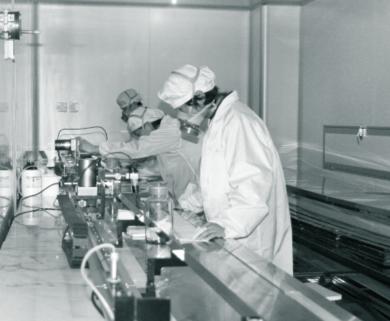
Our company is equipped with an excellent team composed of senior CNC engineers and senior account managers, and experienced application engineers provide a complete set of turnkey projects.



 0086-574-87488065

 Messages


